In all areas that make up the animation pipeline, there is one that many fear due to its complexity, but which is essential for the animation process: Rigging and Weighting.
What is Rigging? Rigging is the process in the animation world that is responsible for creating a control structure for a 3D model, in order to allow the animator to manipulate the model freely.
What is Weighting? Weighting is the process of assigning influence to a 3D model on its geometry, according to the control structure previously created.
STUDENT WORK
This process that we will explain, is what the students of the degree in Animation and Digital Design learned in the subject of Rigging & Weighting. Below are 2 demos of the final work of some students.
Dalia J.
LET’S KNOW A LITTLE MORE IN DEPTH, STEP BY STEP
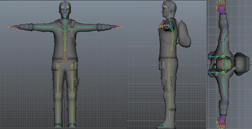
In the Rigging part, the first thing is to create the control structure, which is a skeleton that controls mobility using bones called “joints”.
If we rig a character, a bone construction is made, joints, with which a skeleton is generated that will allow mobility and will be governed by hierarchies according to how the construction and placement of these joints are done.
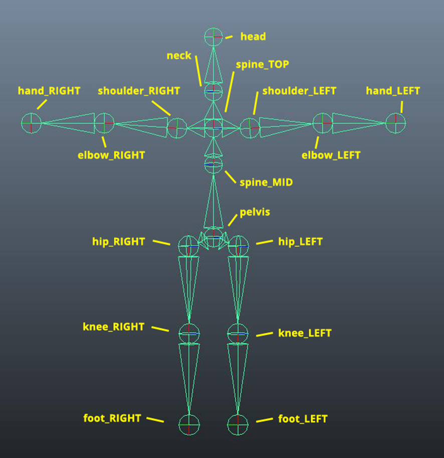
Joints can only influence the modification of translation and rotation, also, they have their own orientation, which, if it’s not assigned correctly, can generate problems in mobility.
LET’S PUT CONTROLLERS
Already having the bone structure, joints, assigned and with appropriate nomenclature, we proceed to assign a controller to each of the joints, which is a spline element, with a figure that serves as a guide to manipulate the joint, without the need to select it directly.
Here comes a very important process which is the hierarchy system, or as it is known to parent one element to another. Basically, it is making one element “A” have control of all the actions of an element “B”.
The appropriate way is to place the spline in the position of each joint, once placed, proceed to delete history and freeze the element, which is simply to set its values to 0.
After having all the spline elements that we already call controllers, we make the process of parenting with a limiter called constraint, the joint with the spline.
So that it is the one that can modify with specific properties the joint.
Once the joint is successfully parented to each spline through its specific constraint, the control structure of a basic rigging is almost complete.
Then the same controllers are assigned hierarchies so that they move according to a correct distribution.
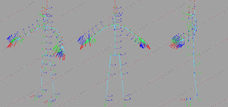
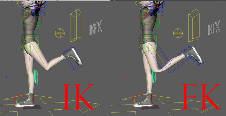
IK AND FK STRUCTURES
The IK (Inverse Kinematics) structure is to give flexible movement to the structure obtaining fluid poses.
The FK (Forward Kinematics) structure is to give controlled and limited movement to the structure obtaining specific poses.
For both structures, the skeleton is created again, but dividing it into parts, column, right side and left side, for legs and arms.
The difference when creating the structures is that, while FK, it is done in the same way as the basic construction of rigging, joint, controller, and constraint.
The IK structure adds elements to make them work better, as it has quite a few freedoms, these are:
Join the joints using IK Handle functions, which allow the joint to move according to the other joints assigned with the handle.
Placement of locators which are elements that will help us give movement control to the IK handles that affect the movement of joints.
By parenting, not with constraints, but now with a pole vector, it will give us limited mobility in one direction, but it will allow more specific mobility of the IK handle.
At the end, controllers are placed in the same way to manipulate the locator and the Ik Handle.
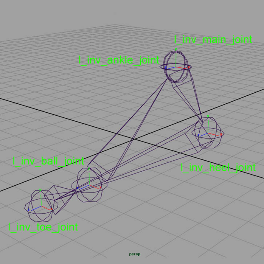
IK REVERSE FOOT
One of the differences in IK and FK structures is that the first one has one more control point, which is another structure of joints which modify the rotation of the foot for better mobility.
These are assigned to the foot controller of the IK structure.
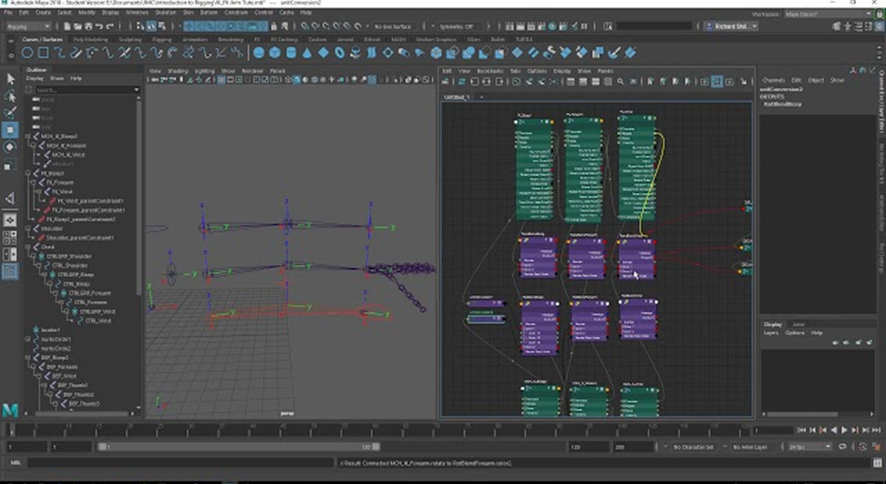
TIME TO MAKE A SWITCH
Already making all the control structures, we proceed to link the IK and FK structures with the initial structure, this is done so that we only have one visible structure but that works as IK or FK mode of the original skeleton.
By selecting joints from the 3 structures, a constraint per joint is made that will influence the control of the IK or FK over the main joints.
Already having linked this step, we proceed to a panel called node editor, in which by connecting nodes of information we make possible the operation and visualization of the structure whether IK or FK for each section made.
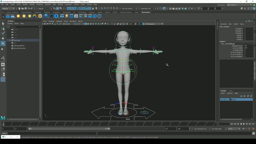
LET’S PUT TOGETHER THE JOINTS WITH THE GEOMETRY (BIND SKIN)
Having everything structured, we proceed to do one last step to parent controllers and later select the visible structure that already carries the IK and FK influence from the original joint, which has influence on all the other joints.
In order to select the geometry of the 3D model and merge that structure and its function with the model.
This process is called “Bind Skin”, which is an automatic calculation that the program does and thus we can modify the control structure that now can affect the geometry with the controllers.
We know that the bind skin has already been done because the joints change their colors, these being a reference to the influence of joint and geometry.
THE PART EVERYONE FEARS, WEIGHTING
Something we must understand is that up to this point, all the previous Rigging process is to generate that control structure that allows me to move my 3D model.
But, since the program makes the automatic calculation, it interprets the weighting on the geometry in a not quite correct way.
For example, if we wanted to move an arm, there is a risk that another part of the body will also move, which is not correct.
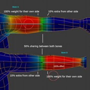
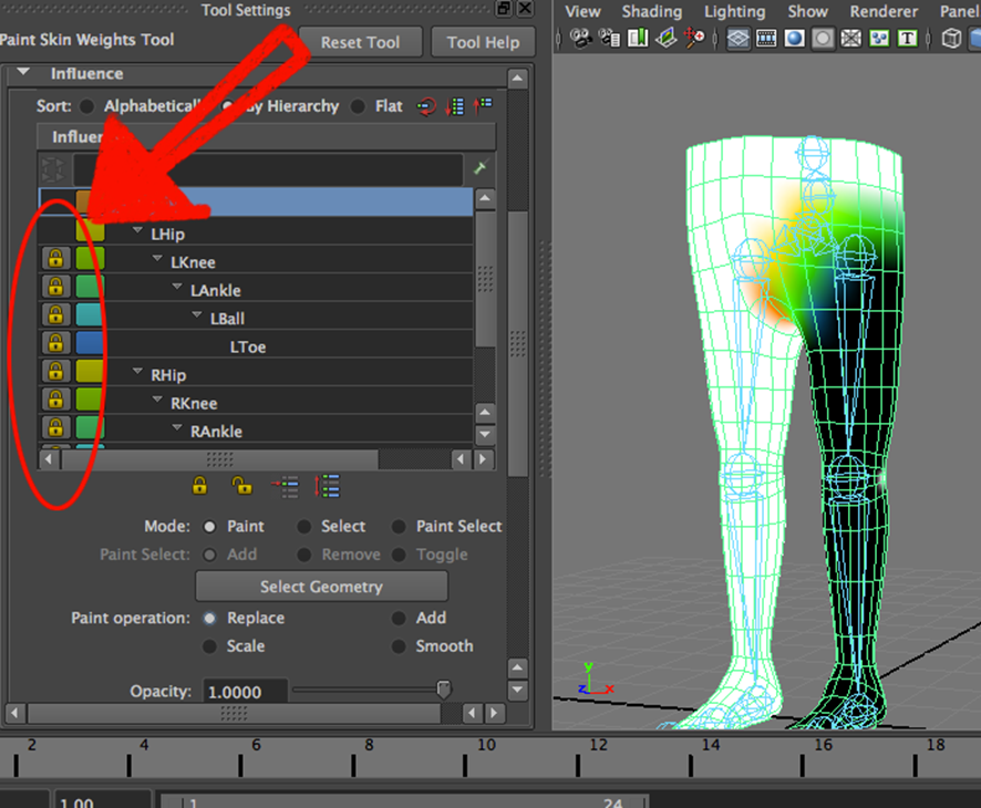
In this part, it is important through the Paint Skin Weights Tool panel, we can select the joints that we combined with the geometry and determine the area of influence that it will have on the model.
This action of selecting joint by joint and determining its influence is known as painting weights, and it is the most problematic part, since the process.
Although simple, is very laborious because we modify geometry and by mistake we can influence areas that we do not want or do the process on a joint that does not correspond to what we influence.
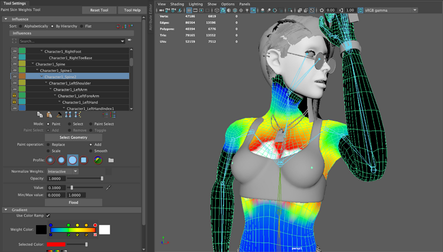
To be able to identify the influence, we can see it in colors, red, orange, yellow, green, and blue.
With red being the highest point of influence that will modify the geometry and blue where it will not affect.
We can also see it in a grayscale, where white is the highest influence and where we no longer count are spaces in black.
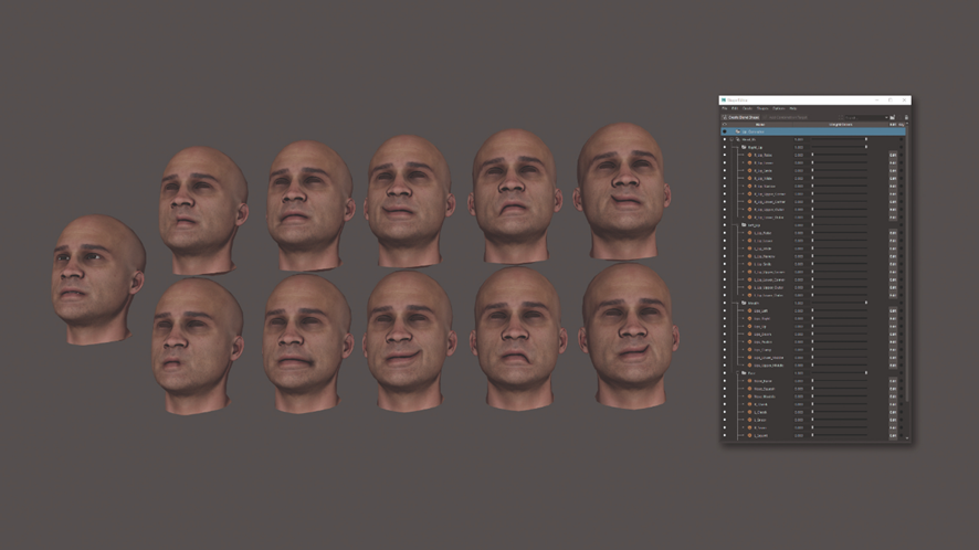
LET’S MAKE DIFFERENT FACES WITH BLEND SHAPES
Up to this point, the modeling has only been rigged & weighted, but the facial is missing.
For this, we have to take the face of the model we have, make several copies, and in each of them, make different facial expressions.
From closing eyes to vowels and emotions, the copies of the face are limited to the number of expressions they want to have on the character.
Already having all the faces with poses, we proceed to link those molds with the original geometry, and that will allow us to combine the information of all the faces in one, that is the blend shape process.
From the Blendshapes panel, we can modify and see the result of the expressions in the original model. And with that, we would finish a basic rigging and weighting.
STUDENT WORK
Here is another student work of Rigging & Weighting
Juan V.
Source: Student´s work
Bachelor’s Degree in Animation and Digital Design
More news about Animation and Digital Design…